SHAFT ALIGNMENT METHODS:
There are three methods of coupling alignment:
1.
Straight edge& feeler gauge
2. Dial
indicators:
Single
dial method
Double
dial method
3. Laser
alignment
COUPLING ALIGNMENT PROCEDURE:
- Coupling alignment involves following steps:
- Ends float assessment and arrest.
- Diagonal Checking for leveling of the equipment on bed.
- Vertical Angular misalignment correction.
- Vertical Offset misalignment correction.
- Horizontal Angular misalignment correction.
- Horizontal Offset misalignment correction.
- Final horizontal angular and offset misalignment correction.
CHECKING SHAFT RELATED RUN OUT:
“TIR” should not exceed 0.025mm per 50mm distance from
bearing”
LEVEL CHECKING: Done for
elimination of clearance between feet of driver and bed.
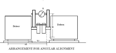
ANGULAR MISALIGNMENT CHECKING:
ANGULAR MISALIGNMENT CHECKING:
Misalignment Existing:
•
At Inboard = L1 / D x A
•
At Outboard = L2 / D x A
L1 = Inboard distance from pivot point in
mm
L2 = Outboard distance from pivot point
in mm
D = Pivot point diameter
A = Net misalignment reading in mm.
Net misalignment = ( L2 - L1
) X A / D
(Add shims at Inboard or outboard depending upon inclination
of the driver)
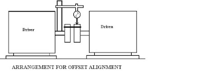
OFFSET MISALIGNMENT CHECKING:
Shims to be added at all the 4 base bolts = TIR / 2
CORRECTION METHOD OF HORIZONTAL OFFSET
MISALIGNMENT:
HORIZONTAL ANGULAR MISALIGNMENT
CORRECTION METHOD:
SHIM INSTALLATION AT REAR FOOT OF MOTOR:
SHIM INSTALLATION AT FRONT FOOT OF MOTOR:
ALIGNMENT CORRECTION WITH FEELER GAUGE
AND SCALE:
VERTICAL PUMP ALIGNMENT:
SHIMS:
- Try to use a maximum of 4 or less shims under each foot.
- It’s not always possible, but tries to minimize the number of shims per foot.
- Use pre-cut stainless steel shims. You can’t cut them for less than you can buy them.
- When you insert shims under the foot, slide them all the way in, then back them out 5mm, so the bolt threads don’t bend them.
- Don’t reuse painted or badly bent shims.
- Be careful. A 0.05mm shim can cut you like a knife.
- Keep them neat.
DIAL INDICATORS:


